


Downloads
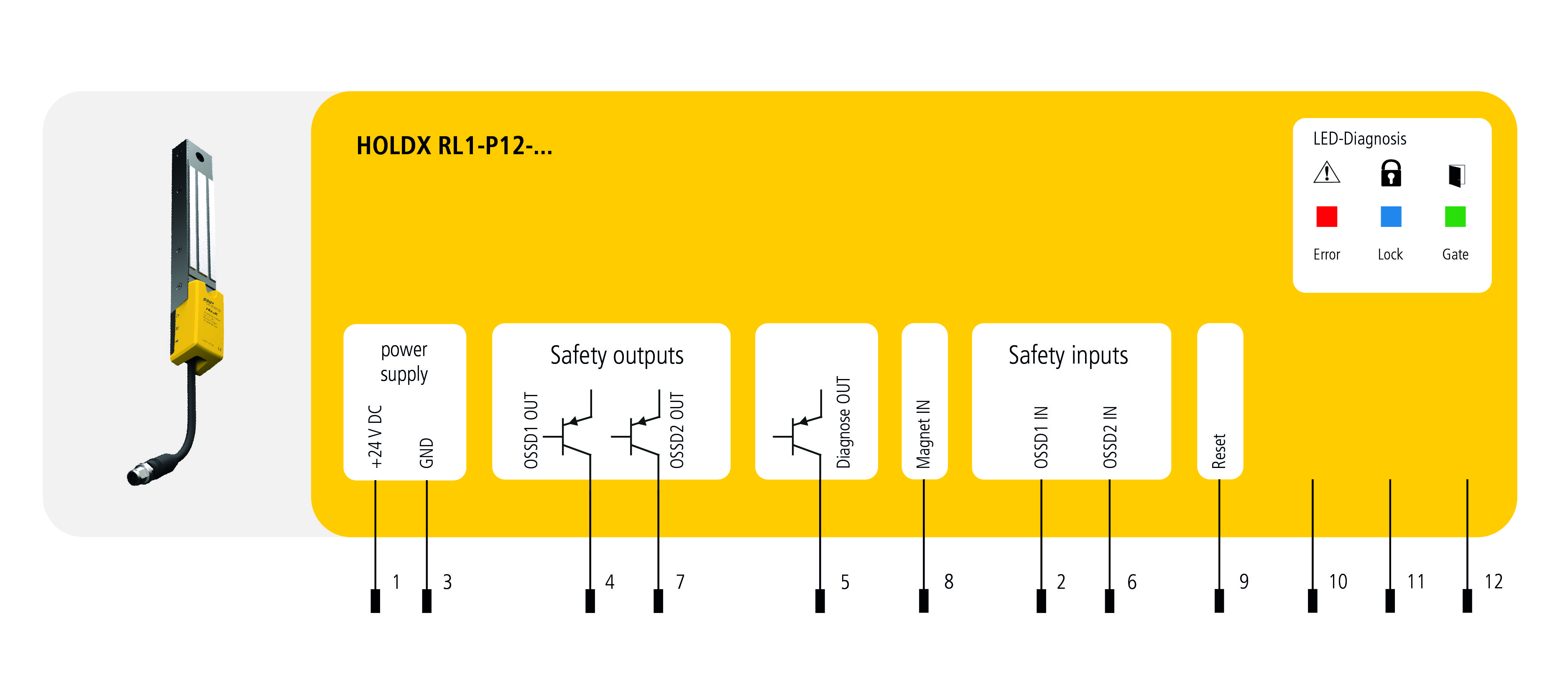
HOLDX RL1-P12-S-B
Process guard lock standard coding, Pigtail M12 12-pin, 1200 N locking force
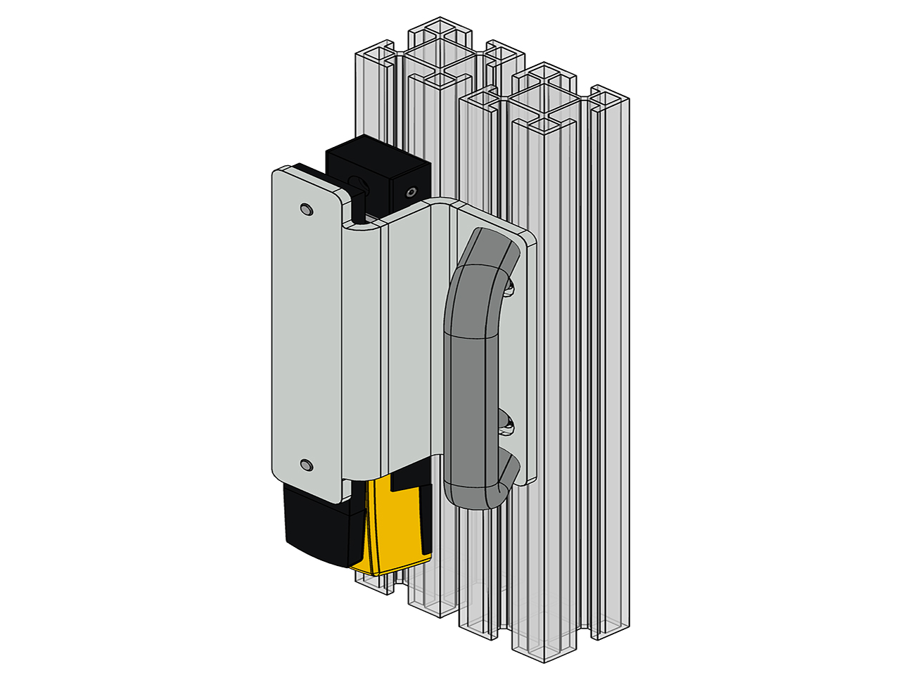
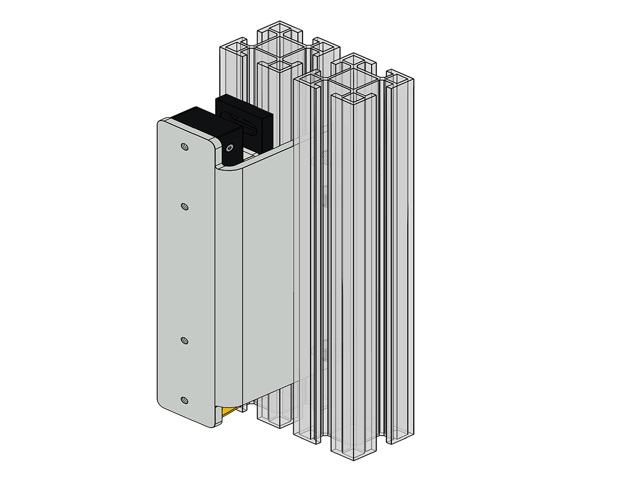
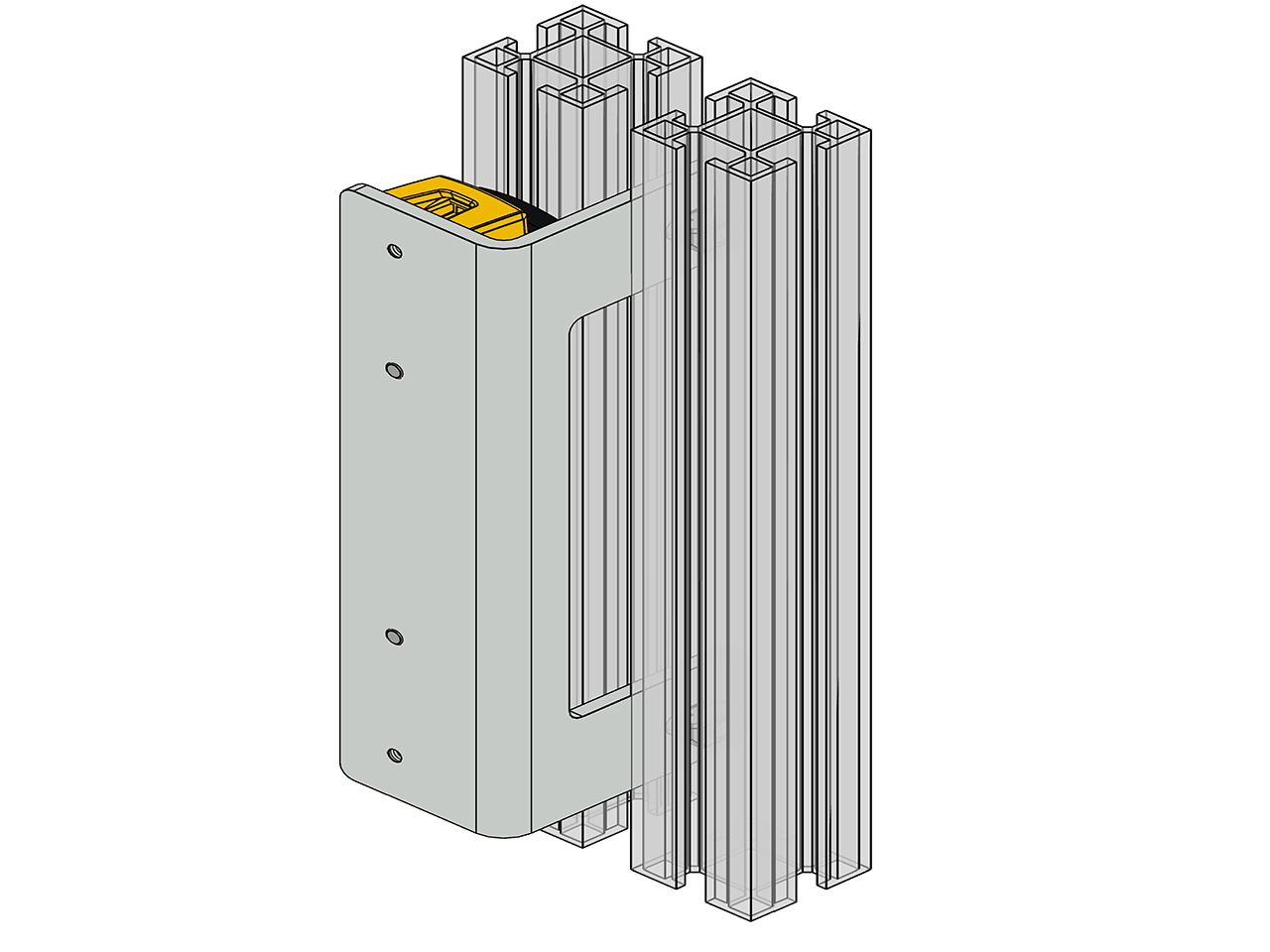
Ideal for large doors. Thanks to the locking force of 1200 N, the HOLDX RL prevents doors from tearing open. With a slim width of only 35 mm, the guard locking is ideal for space-saving installation on aluminum profile systems. Like the HOLDX RS, the guard locking has also has a permanent magnet of 50 N, which prevents a door from opening.
General data
Type designation
RL1-P12-S-B
Item number
SP-X-71-001-22
Coding levels
Standard
Safety relevant data
Category (EN ISO 13849-1: 2015)
Cat.4
SIL (IEC 61508: 2010)
SIL3
- Hardware fault tolerance
HFT1
- PFHd
2,24 x 10⁻⁹
Service life (EN IEC 62061)
20 Years
Switching current per safety output max.
100 mA (DC-12/DC-13)
Safety data
Performance Level (EN ISO 13849-1: 2015)
PLe
SIL (EN IEC 62061: 2005 + A2: 2015)
SIL CL3
Environmental conditions
Max. storage temperature
-20 °C ... +70 °C
Max. operating temperature
-20 °C ... +55 °C
Protection class
IP67
Electrical data
Supply voltage
24 VDC (+10/-15%)
Rated impulse withstand voltage Uimp
1 kV
Power consumption (incl. OSSD outputs
17 W
Rated current (on 24 VDC)
645 mA
No-load current I0
60 mA
Amount safety inputs
1 x 2-channels
Current consumption per input max.
2,75 mA
Current consumption input magnet ON
1,2 mA
Voltage drop safety output (Ud)
0,75 V
Amount OSSD safety output
1 x 2-channels
Safety output - output type
Transistor (PNP)
Residual current safety output (Ir)
0,5 mA
Load capacitive reactance safety output max.
20 nF
Amount diagnosis output
1
Diagnosis output- output type
Transistor (PNP)
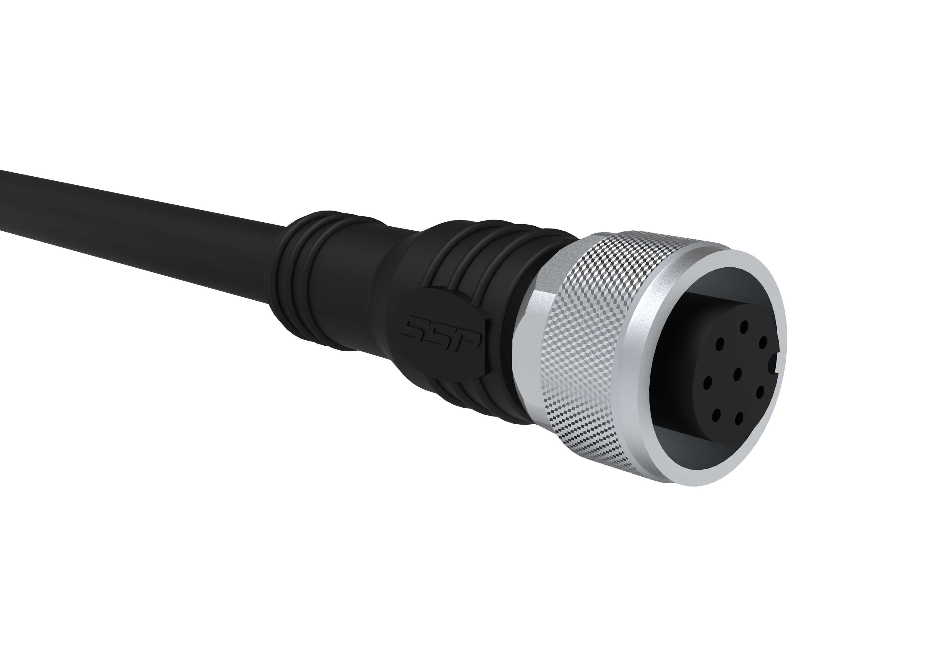
Connection type
M12 12-pin, Pigtail 200 mm
Series connection for safe In- and Outputs
max. 30 process locks
Protection class power supply
III
Switching current per diagnosis output max.
100 mA
Design / Connections
1x Pigtail 12-pin
Risk time
75 ms ms
Mechanical data
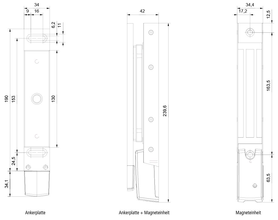
Dimensions
Width
34 mm
Length
240 (without cabel) mm
Height
31 mm
Weight
375 g
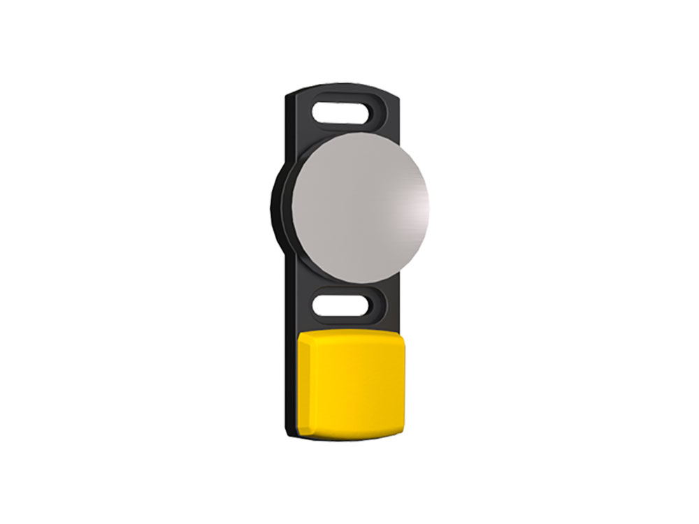
Dimensions of anchor plate
Width of anchor plate
34,4 mm
Length of anchor plate
224,1 mm
Height of anchor plate
20.1 mm
Locking force electromagnet
600 N
Permanent magnet
50 N
Smart resting force
0 / 30 / 50 N
Weight process lock
725 g
Weight anchor plate
475 g
Torque (mounting screw) process lock
6 Nm
Torque (mounting screw) anchor plate
6 Nm
Mounting
Screwing with raised head screw M6 Torx with pin
Material housing lock
PBT GF30, Aluminium eloxated black, TPE, PC
Shock resistance
30 g / 11 ms
Vibration resistance
1 g, 5-150 Hz
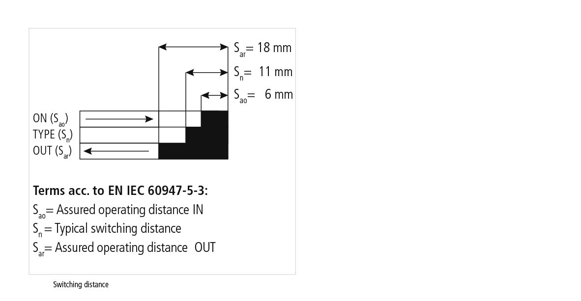
Switching distance according to DIN EN 60947-5-3:2014-12
Assured switching distance ON S(ao)
6 mm
Assured switching distance OFF S(ar)
18 mm
Typical switching distance S(n)
11 mm
Repeat accuracy R switching distance
<0,5 mm
Hysteresis
2 mm
Generall periods
Readiness delay t(v)
5000 ms
Start delay acctuator t(on)
75 ms
Safety function times
Switch-off reaction time inputs
max.3 ms
Switch-off reaction time anchor plate - Outputs t(off)
max. 75 ms
Test impulse length OSSD Sicherheitsausgänge
0.3 ms
Electrical drawings
Connection drawing
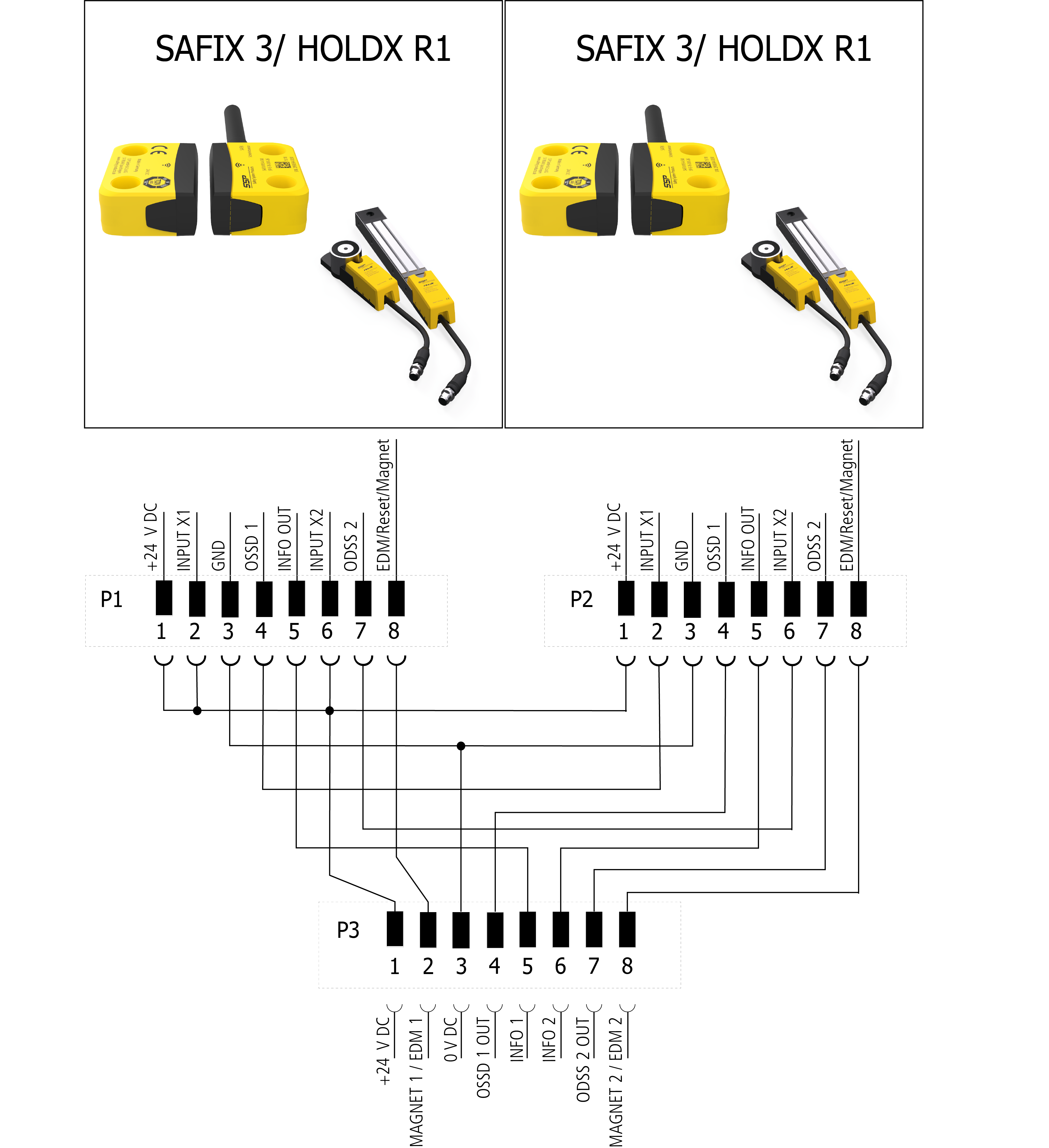
Connection example 1
Drawings
Approach
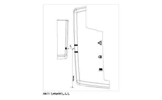
Dimensions
Switching gap
Approach direction
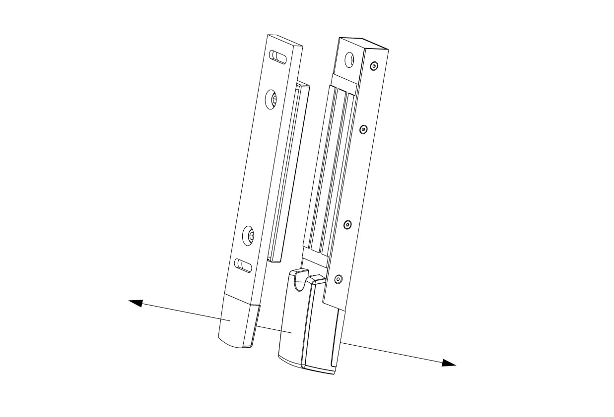
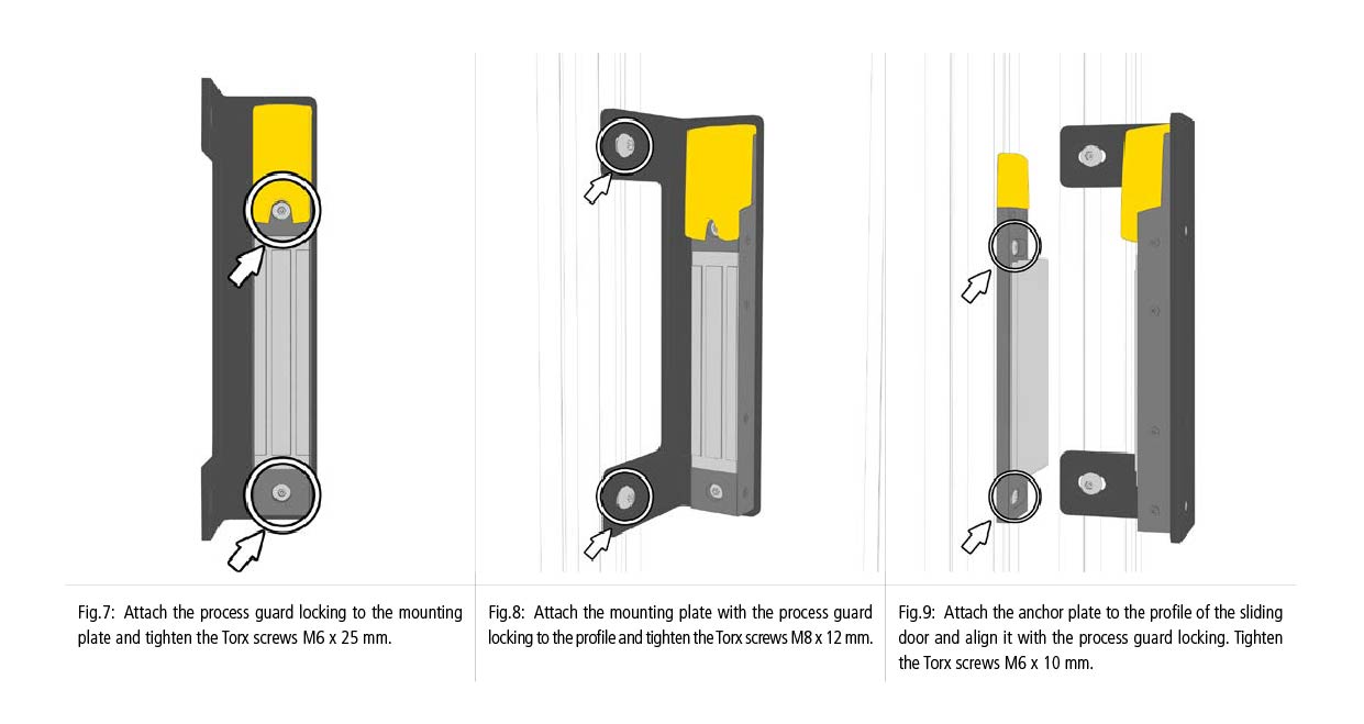
Assembly
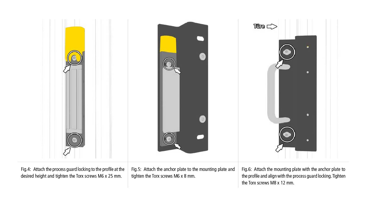
Assembly 2