


Your advantages
- 14 I/O's as safety Inputs or redundant OSSD- Outputs
- wireless Interface for safe communication, programming & diagnosis
- IP65
- 40mm width for aluminium safety fence systems
Downloads
S14LDRB-H0A-E2-I1-I1-I1-Q1A0-Q2A0-Q3C0-Q4I0-W40
Safety Simplifier | for SAFIX
With the Safety Simplifier we take safety where it is needed and we provide safety where it is needed with the Safety Simplifier and make it easier for you to develop user-friendly safety systems, such as on access doors. Simply connect up your sensors, locking systems or light curtains. Select the required push button and/or emergency stop button and you have a complete safety solution with analysis and diagnosis functions. his data is wirelessly transmitted via another Safety Simplifier or directly transmitted to your existing system in a fail-safe manner.
General data
Type designation
S14LDRB-H0A-E2-I1-I1-I1-Q1A0-Q2A0-Q3C0-Q4I0-W40
Item number
SP-X-89-100-09
Functional type
safety PLC with safe wireless interface, internal antenna
Body Material
PC + ABS
Button position 1
Type designation
E2
Function type
Emergency- Stop- Button
Button position 2
Type designation
I1
Function type
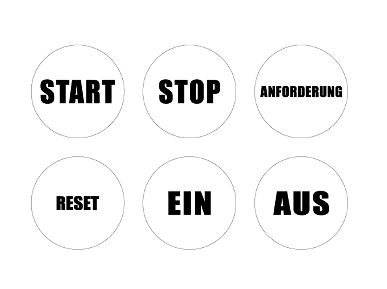
Illuminated Button
Button position 3
Type designation
I1
Function type
Illuminated Button
Button position 4
Type designation
I1
Function type
Illuminated Button
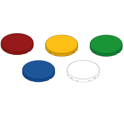
Colour
red, yellow, green, blue, white
Connection
- Position 1
Q1A0 - Connection bottom left with cover
- Position 2
Q2A0 - Connection top left with cover
- Position 3
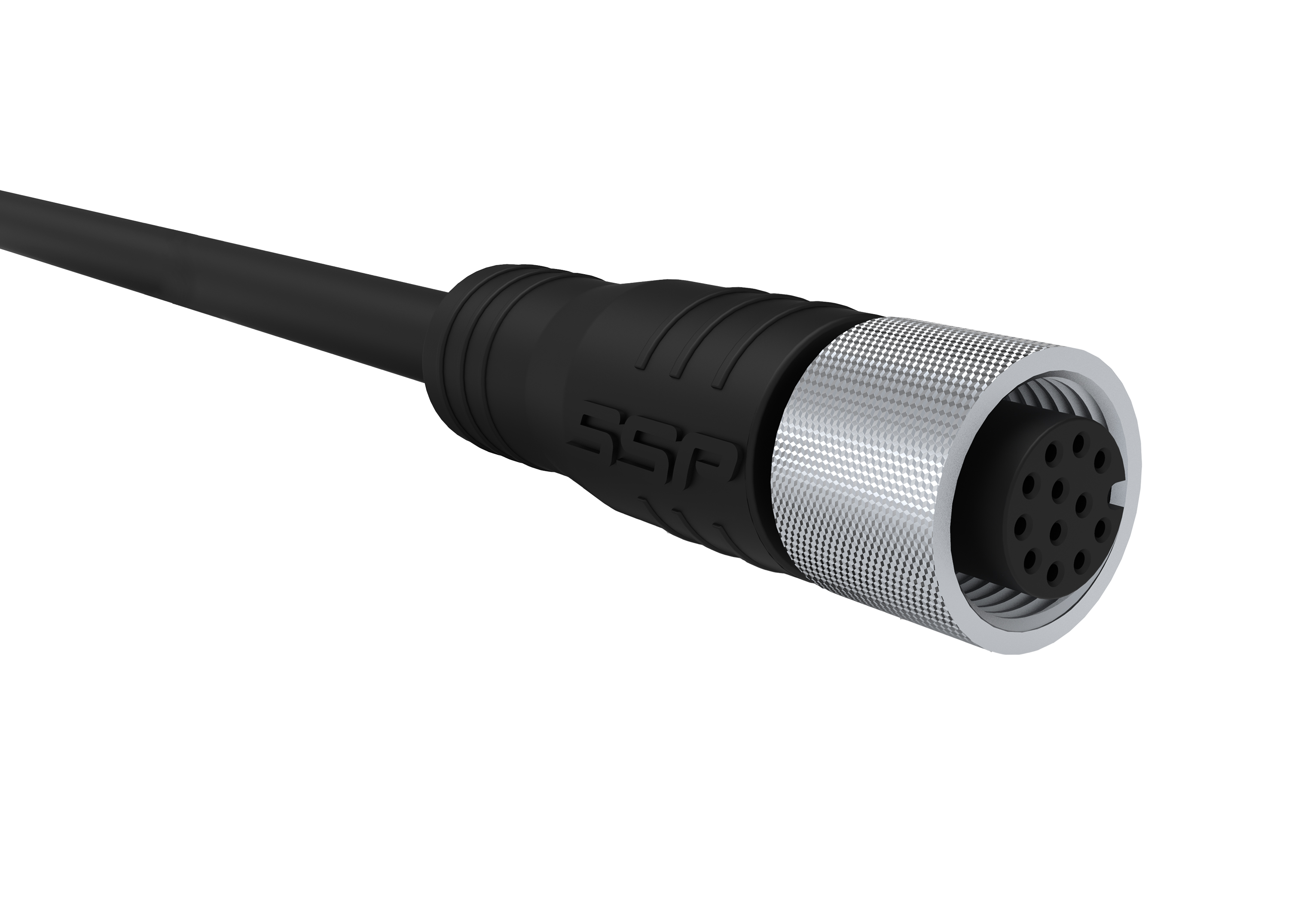
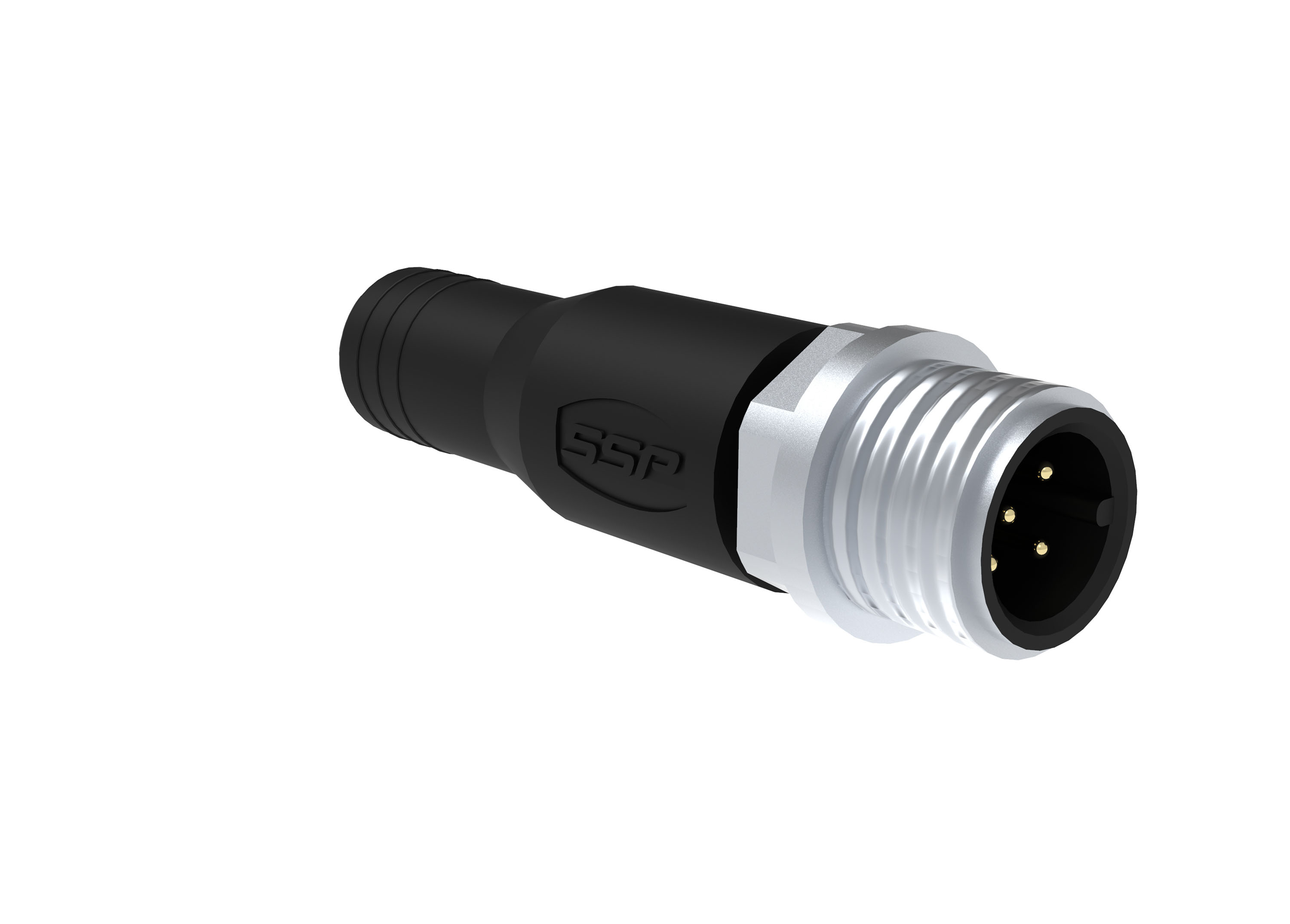
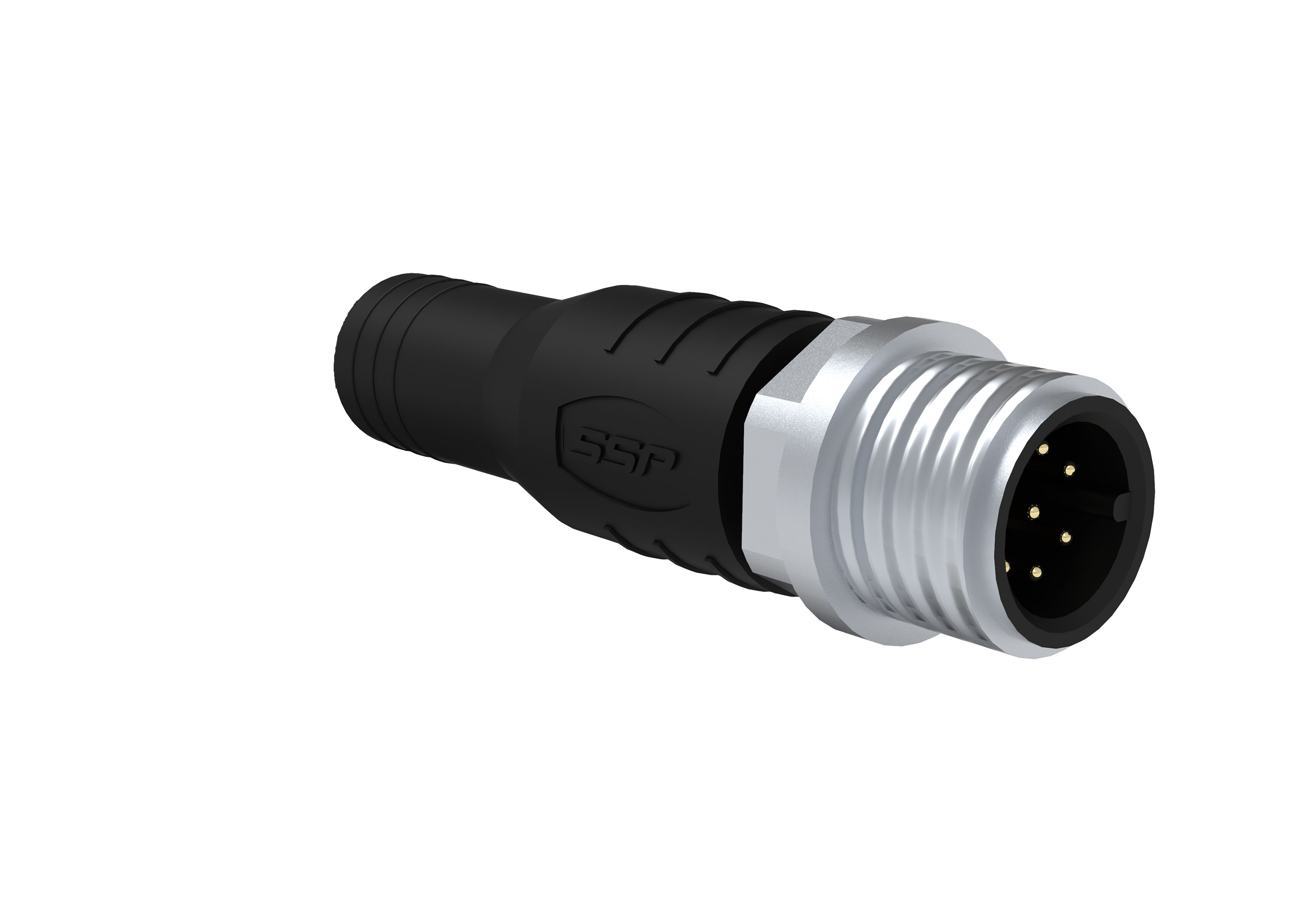
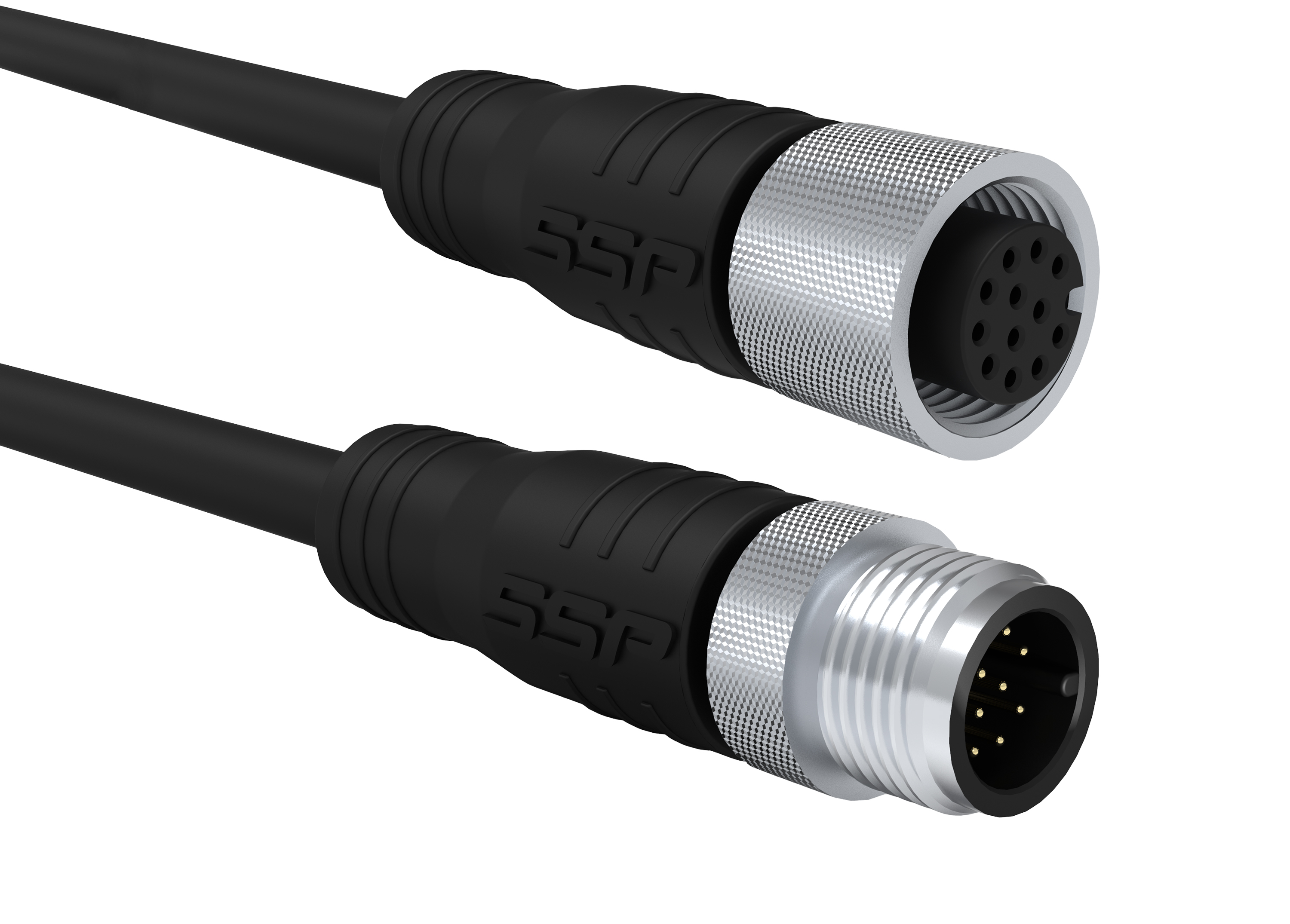
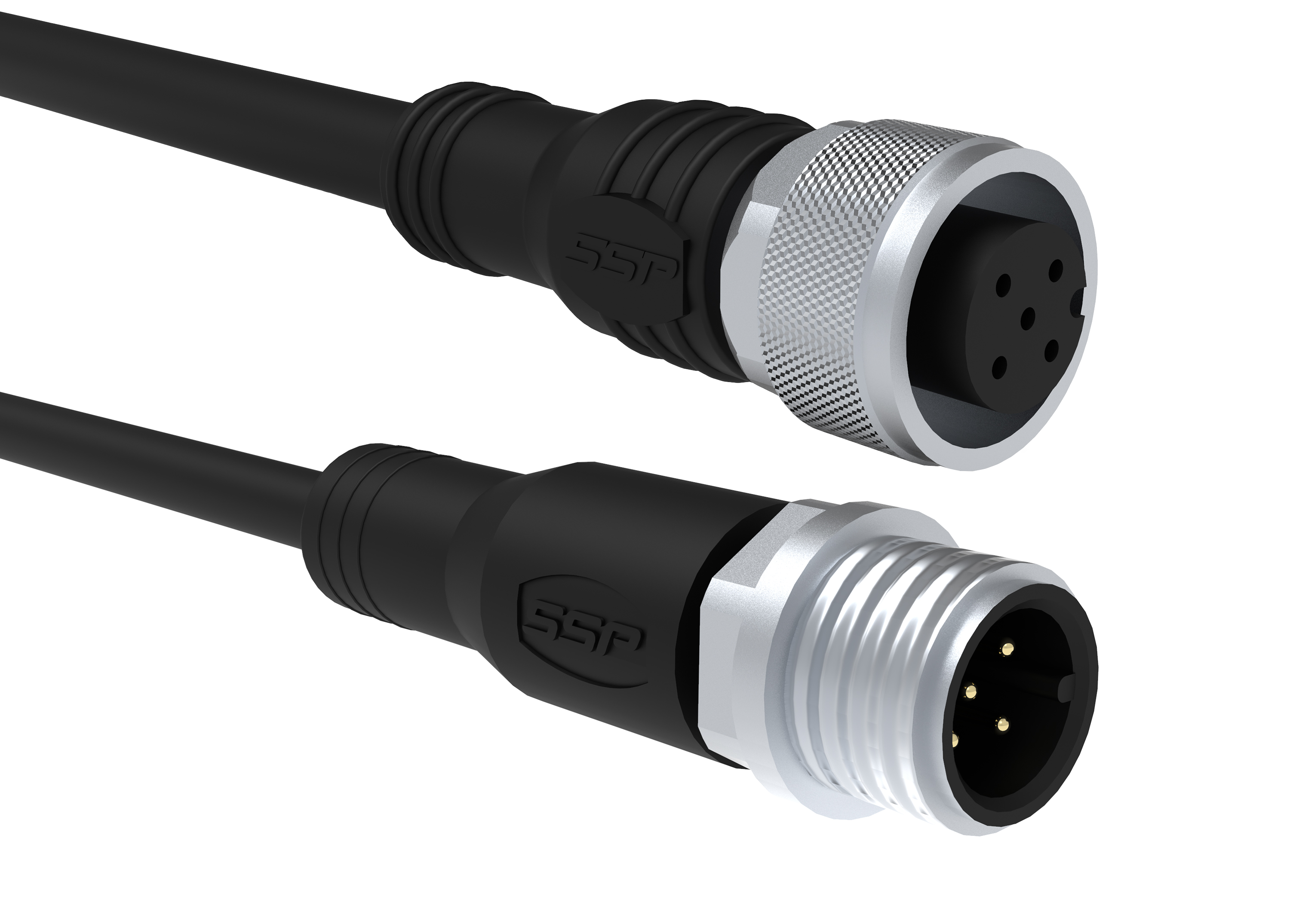
Q3C0- male connector M12 5-Pin
- Position 4
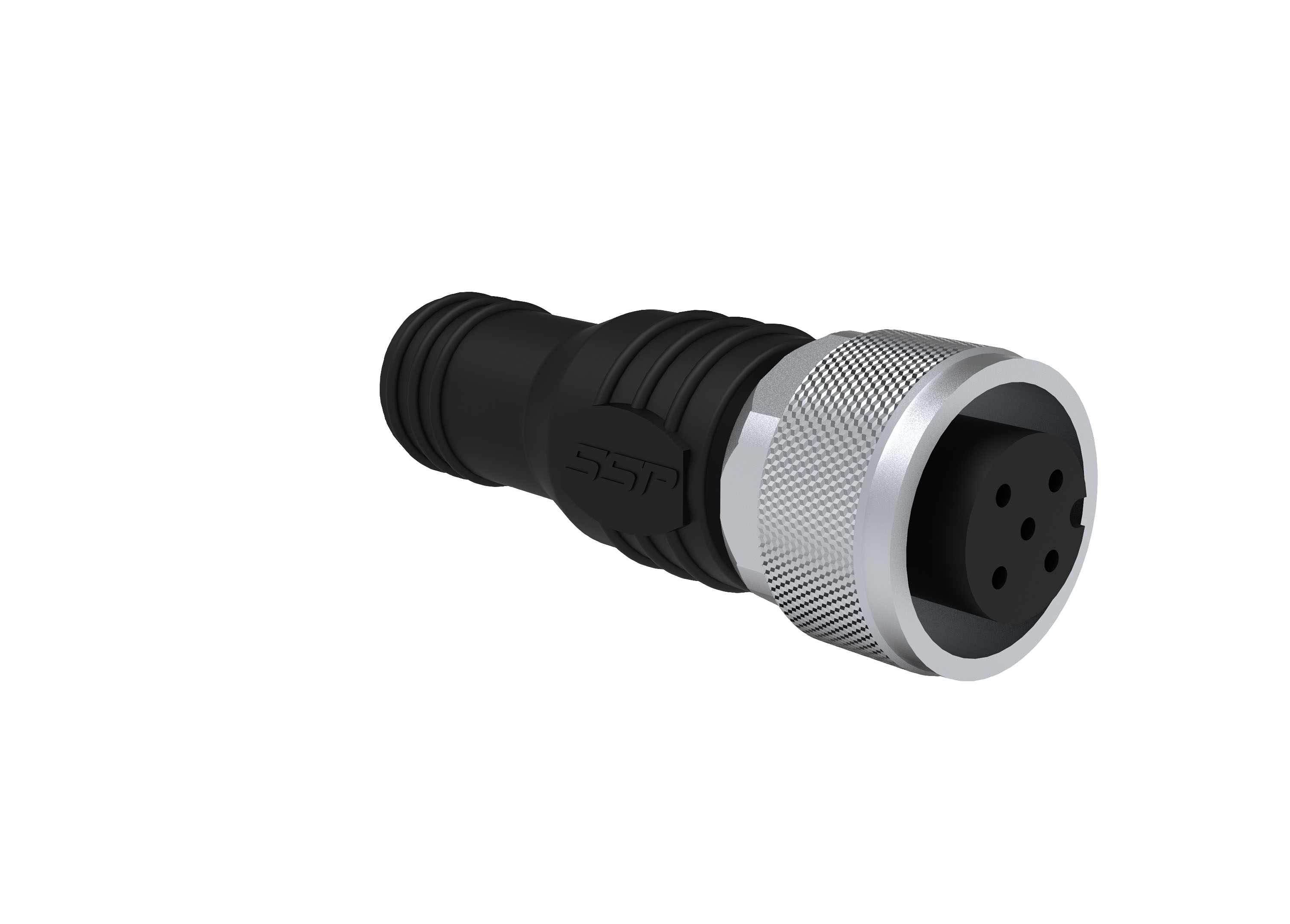
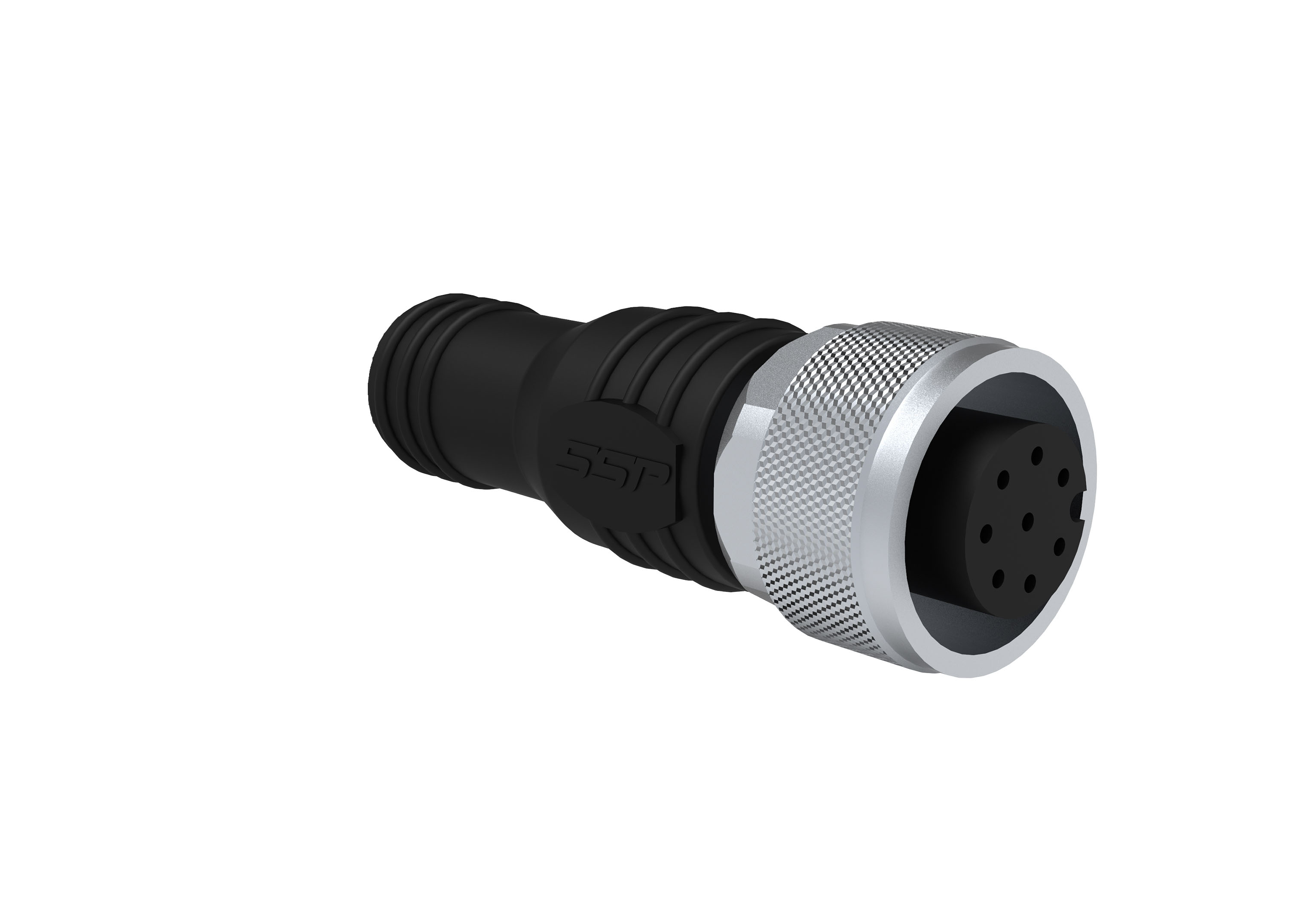
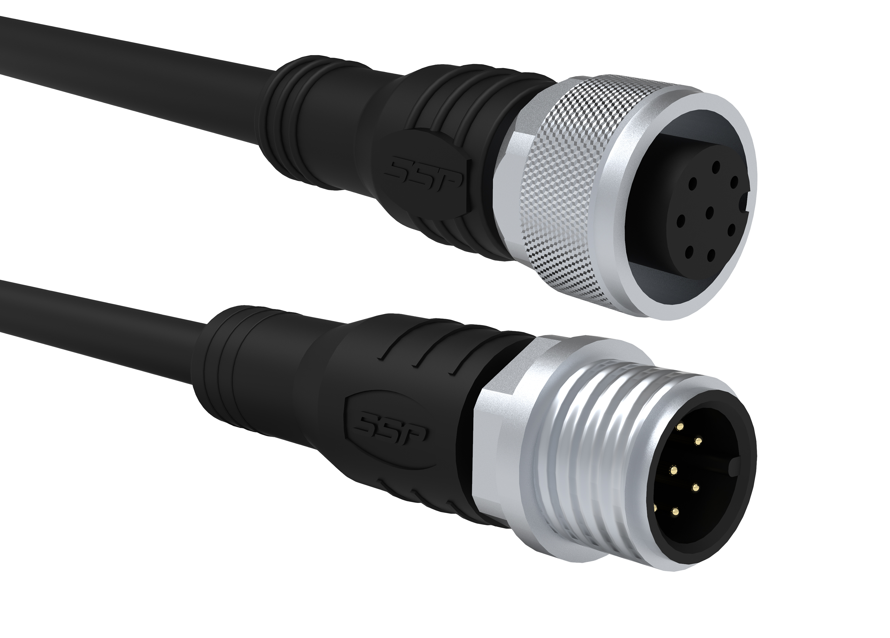
Q4I0 - female connector M12 8-pin
Safety data
CPU
- EN ISO 13849-1: 2008
Category 4
- IEC 61508-2
SIL CL 3
- EN 62061 PFHD [1/h]
✔
- EN ISO 13849-1: 2008 TM [Year]
20
1-channel input
- EN ISO 13849-1: 2008
Category 2
- IEC 61508-2
SIL CL 2
- EN 62061 PFHD [1/h]
✔
- EN ISO 13849-1: 2008 TM [Year]
20
2-channel input
- EN ISO 13849-1: 2008
Category 4
- IEC 61508-2
SIL CL 3
- EN 62061 PFHD [1/h]
✔
- EN ISO 13849-1: 2008 TM [Year]
20
1-channel OSSD output
- EN ISO 13849-1: 2008
Category 2
- IEC 61508-2
SIL CL 2
- EN 62061 PFHD [1/h]
✔
- EN ISO 13849-1: 2008 TM [Year]
20
2- channel OSSD Output
- EN ISO 13849-1: 2008
Category 4
- IEC 61508-2
SIL CL 3
- EN 62061 PFHD [1/h]
✔
- EN ISO 13849-1: 2008 TM [Year]
20
2- channel relais output
- EN ISO 13849-1: 2008
Category 4
- EN 62061 SIL CIL
SIL CL 3
- EN 62061 PFHD [1/h]
✔
- EN ISO 13849-1: 2008 TM [Year]
20
Approvals
CE, TÜV
Environmental conditions
Max. storage temperature
-20°C... +65 °C
Max. operating temperature
-20°C... +65 °C
Protection class
IP65
Electrical data
Technical data wireless safety
- max. amount of safe wireless channels
16
Channels
- Channel 1
2405 MHz
- Channel 2
2410 MHz
- Channel 3
2415 MHz
- Channel 4
2420 MHz
- Channel 5
2425 MHz
- Channel 6
2430 MHz
- Channel 7
2435 MHz
- Channel 8
2440 MHz
- Channel 9
2445 MHz
- Channel 11
2455 MHz
- Channel 10
2450 MHz
- Channel 12
2460 MHz
- Channel 13
2465 MHz
- Channel 14
2470 MHz
- Channel 15
2475 MHz
- Channel 16
2480 MHz
- amount of clamps
32
Supply voltage
10 - 30 V
Current consumption
110 mA with LED display
Conductor cross section
- single wire
0,08 ... 0,5 mm²
- fine wire
0,08 ... 0,5 mm²
- fine wired (wire sleeve without plastic collar)
0,25 mm²
stripping length
5-6 mm
configurable In-/ Outputs
14 semiconductor In-/ Outputs with help of software configurable
Amount of safe inputs
max. 14
Amount of safe semi-conductors OSSD outputs
max. 14
Amount of semi-conductors auxilliary outputs
max. 14
Amount of semi-conductors clock outputs
max. 8
Input current
HIGH 2,4 mA ... 3,8 mA LOW -2,5 mA ... 2,1 mA
Output type
PNP- Semiconductor
Output voltage
Operating voltage UB -0,5 V
Seperate output current
max. 600 mA (with UB 24 V)
Total output current
max. 2 A (with UB 24 V)
Button position 1
Type designation
E2
Function type
Emergency-Stop-Button
Switch type
2 Openers + LED
Bounce time NO
<10 ms
Bounce time NC
<10 ms
Break contact force opening
according to EN60947-5-1 Anh-K
Illumination
LED
mechanical lifespan
50.000 switching cycles
electrical lifespan
50.000 switching cycles
B10d- Value
250.000
Button position 2
Type designation
I1
Function type
Illuminated Button
Switch type
1 closing device + LED
Break contact force opening
according to EN60947-5-1 Anh-K
Illumination
LED
mechanical lifespan
30.000 switching cycles
electrical lifespan
30.000 switching cycles
Button position 3
Type designation
I1
Function type
Illuminated Button
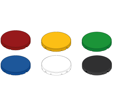
Colour
red, yellow, green, blue, white
Switch type
1 closing device + LED
Break contact force opening
according to EN60947-5-1 Anh-K
Illumination
LED
mechanical lifespan
30.000 switching cycles
electrical lifespan
30.000 switching cycles
Button position 4
Type designation
I1
Function type
Illuminated Button
Colour
red, yellow, green, blue, white
Switch type
1 closing device + LED
Bounce time NO
<10 ms
Bounce time NC
<10 ms
Break contact force opening
according to EN60947-5-1 Anh-K
Illumination
LED
mechanical lifespan
30.000 switching cycles
electrical lifespan
30.000 switching cycles
General data
Memory card
Installation of a memory card MEM SP-N-88-001-93 possible
Programming connection
Micro USB
Type terminal connection
clamp terminals
- fine wired (wire sleeve with plastic collar)
0,08 ... 0,5 mm²
Input voltage
HIGH 75% from UB (adjustable by software) LOW 25% from UB (adjustable by software)
Technical data inputs
Technical data safe OSSD outputs, auxilliary and test pulse outputs
Short-circuit proof
Yes
Mechanical data
Installation opening of buttons
22,5 mm
Type of housing
H0A
Dimensions
Height
44 mm
Length
253 mm
Width
42 mm
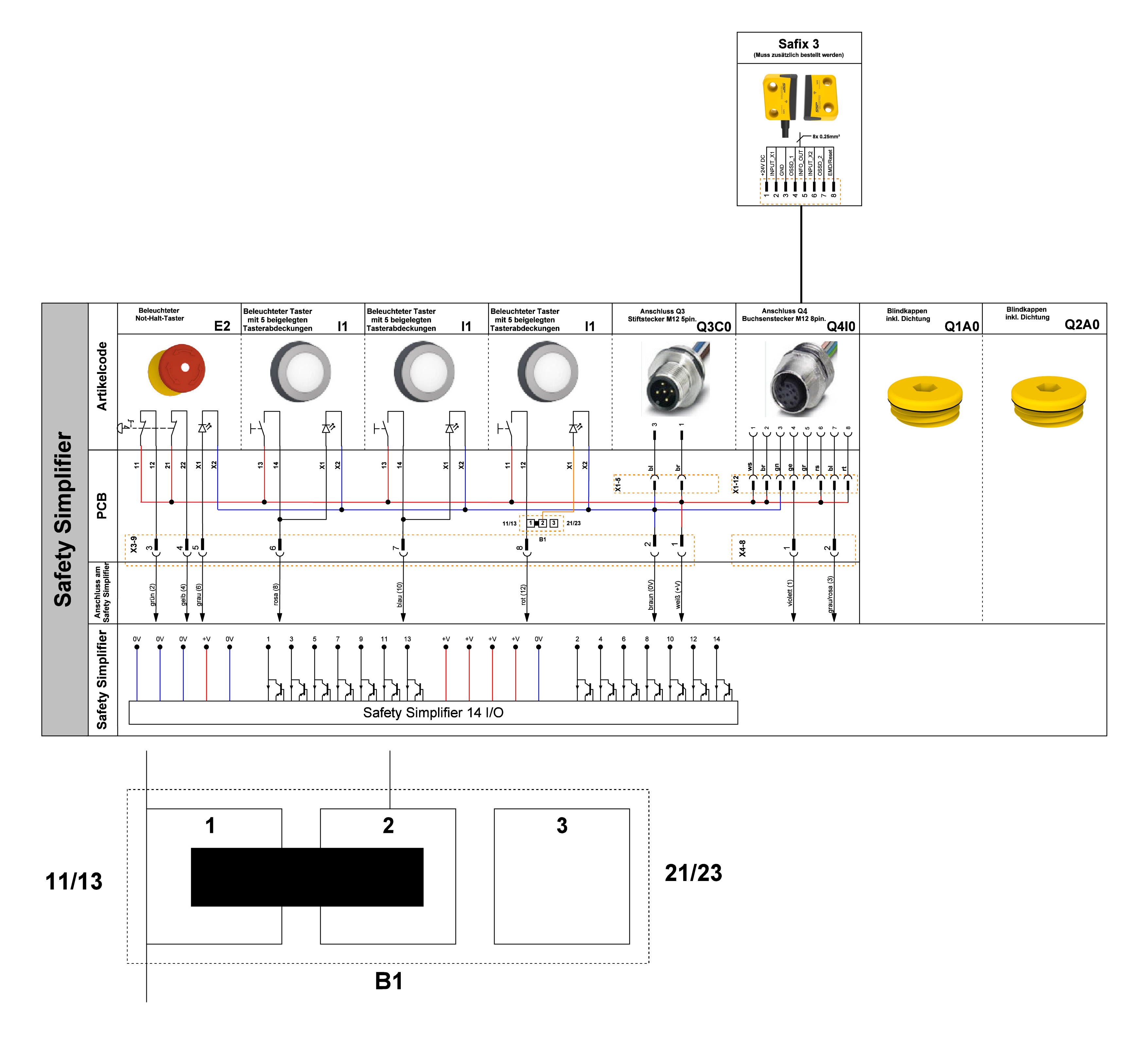
Electrical drawings
Connection example 1