


Your advantages
- 14 I/O's as safety Inputs or redundant OSSD- Outputs
- wireless Interface for safe communication, programming & diagnosis
- IP65
- 40mm width for aluminium safety fence systems
Downloads
S14LDRB-H0A-E2-I1-I1-I1-Q1A0-Q2M0-Q3C0-Q4J0-W60
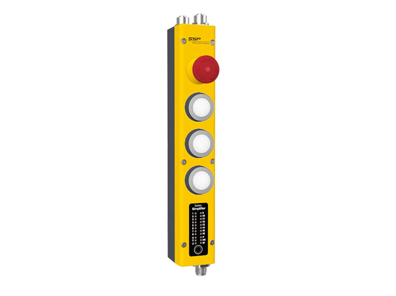
Safety Simplifier | for tGard and SAFIX 3
- S14LDRB-H0A: Safety Simplifier with 14 I/Os plus 2 double relais outputs
- LED Diagnosis for simple handling safe wireless communication
Box Bottom:anthracite, no holes
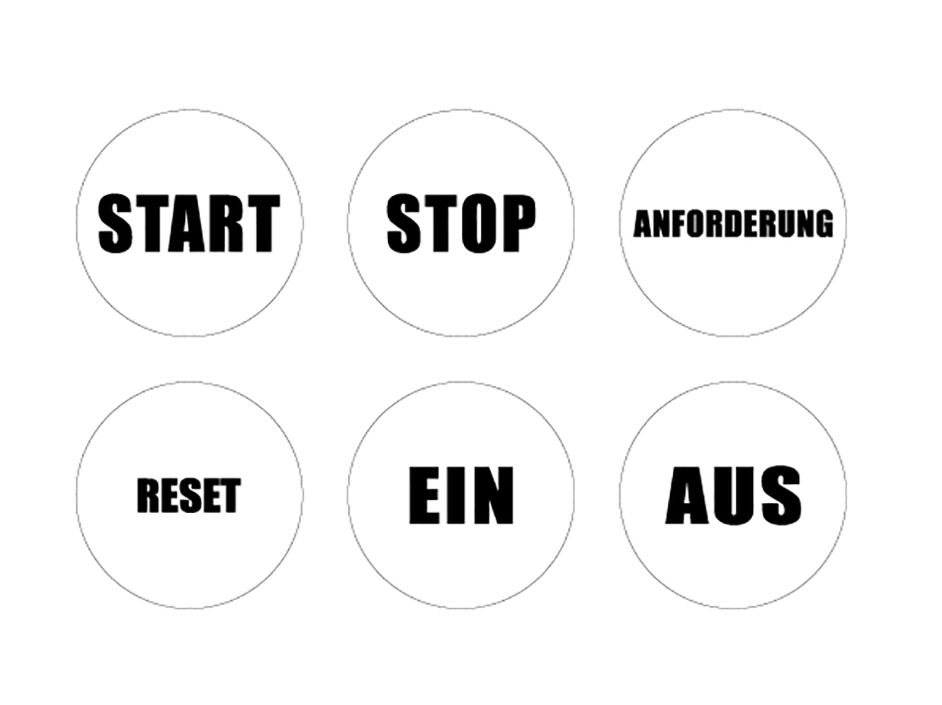
Top of box: yellow;possibillity to mount four buttons - E2: E-Stop (twist reset), Safety s 2 x NC, illuminated
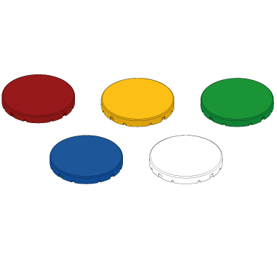
- I1: Illuminated pushbutton (5 colours), Safety 1 x NO
- I1: Illuminated pushbutton (5 colours), Safety 1 x NO
- I1: Illuminated pushbutton (5 colours), Safety 1 x NO
- Q1A0: connection bottom left side including plug
- Q2M0: connection top left side including socket plug M12-8 Pin for Safix
- Q3C0: connection bottom right side including male plug M12-5 Pin
- Q4J0: connection top right side including socket plug M12-12 Pin for tGard SMDU
- W60: pre wired
General data
Type designation
S14LDRB-H0A-E2-I1-I1-I1-Q1A0-Q2M0-Q3C0-Q4J0-W60
Item number
SP-X-89-100-35
Functional type
safety PLC with safe wireless interface, internal antenna
Body Material
PC + ABS
Button position 1
Type designation
E2
Function type
Illuminated Emergency-Stop-Button , 2 x NC
Button position 2
Type designation
I1
Function type
Illuminated button , 1x NO (5 x button caps included)
Button position 3
Type designation
I1
Function type
Illuminated button , 1x NO (5 x button caps included)
Button position 4
Type designation
I1
Function type
Illuminated button , 1x NO (5 x button caps included)
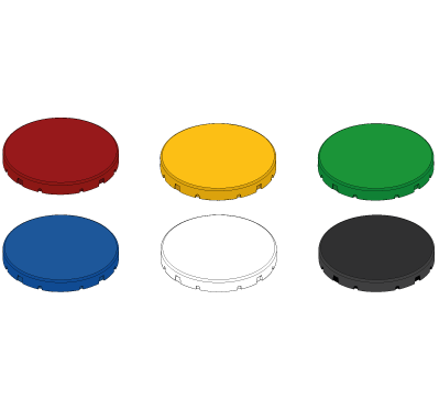
Colour
red, yellow, green, blue, white
Connection
- Position 1
Q1A0 - Connection bottom left with cover
- Position 2
Q2M0 - Connection top left including female plug M12 8-pin forSAFIX 3
- Position 3
Q3C0- connection bottom right side including male plug M12-5 Pin
- Position 4
Q4S0 - connection top right side including socket plug M12-8 Pin for ATOM
Safety data
CPU
- EN ISO 13849-1: 2008
Category 4
- IEC 61508-2
SIL CL 3
- EN 62061 PFHD [1/h]
✔
- EN ISO 13849-1: 2008 TM [Year]
20
1-channel input
- EN ISO 13849-1: 2008
Category 2
- IEC 61508-2
SIL CL 2
- EN 62061 PFHD [1/h]
✔
- EN ISO 13849-1: 2008 TM [Year]
20
2-channel input
- EN ISO 13849-1: 2008
Category 4
- IEC 61508-2
SIL CL 3
- EN 62061 PFHD [1/h]
✔
- EN ISO 13849-1: 2008 TM [Year]
20
1-channel OSSD output
- EN ISO 13849-1: 2008
Category 2
- IEC 61508-2
SIL CL 2
- EN 62061 PFHD [1/h]
✔
- EN ISO 13849-1: 2008 TM [Year]
20
2- channel OSSD Output
- EN ISO 13849-1: 2008
Category 4
- IEC 61508-2
SIL CL 3
- EN 62061 PFHD [1/h]
✔
- EN ISO 13849-1: 2008 TM [Year]
20
2- channel relais output
- EN ISO 13849-1: 2008
Category 4
- EN 62061 SIL CIL
SIL CL 3
- EN 62061 PFHD [1/h]
✔
- EN ISO 13849-1: 2008 TM [Year]
20
Approvals
CE, TÜV
Environmental conditions
Max. storage temperature
-20°C... +65 °C
Max. operating temperature
-20°C... +65 °C
Protection class
IP65
Electrical data
Technical data wireless safety
- max. amount of safe wireless channels
16
Channels
- Channel 1
2405 MHz
- Channel 2
2410 MHz
- Channel 3
2415 MHz
- Channel 4
2420 MHz
- Channel 5
2425 MHz
- Channel 6
2430 MHz
- Channel 7
2435 MHz
- Channel 8
2440 MHz
- Channel 9
2445 MHz
- Channel 11
2455 MHz
- Channel 10
2450 MHz
- Channel 12
2460 MHz
- Channel 13
2465 MHz
- Channel 14
2470 MHz
- Channel 15
2475 MHz
- Channel 16
2480 MHz
- amount of clamps
32
Supply voltage
10 - 30 V
Current consumption
110 mA with LED display
Conductor cross section
- single wire
0,08 … 0,5 mm²
- fine wire
0,08 … 0,5 mm²
- fine wired (wire sleeve without plastic collar)
0,25 mm²
stripping length
5-6 mm
configurable In-/ Outputs
14 semiconductor In-/ Outputs with help of software configurable
Amount of safe inputs
max. 14
Amount of safe semi-conductors OSSD outputs
max. 14
Amount of semi-conductors auxilliary outputs
max. 14
Amount of semi-conductors clock outputs
max. 8
Input current
HIGH 75% from UB (adjustable by software) LOW 25% from UB (adjustable by software)
Output type
PNP- Semiconductor
Output voltage
Betriebsspannung UB -0,5 V
Seperate output current
max. 600 mA (with UB 24 V)
Total output current
max. 2 A (with UB 24 V)
Button position 1
Type designation
E2
Function type
Emergency-stop-button
Switch type
2 Openers + LED
Bounce time NO
<10 ms ms
Bounce time NC
<10 ms
Break contact force opening
according to EN60947-5-1 Anh-K.
Illumination
LED
mechanical lifespan
50.000 switching cycles
electrical lifespan
50.000 switching cycles
Button position 2
Type designation
I1
Function type
Illuminated Button
Switch type
1 closing device + LED
Bounce time NO
< 10
Bounce time NC
< 10
Break contact force opening
according to EN60947-5-1 Anh-K.
Illumination
LED
mechanical lifespan
30.000 switching cycles
electrical lifespan
30.000 switching cycles
Button position 3
Type designation
I1
Function type
Illuminated Button
Colour
red, yellow, green, blue, white
Switch type
1 closing device + LED
Bounce time NO
< 10
Bounce time NC
< 10
Break contact force opening
according to EN60947-5-1 Anh-K.
Illumination
LED
mechanical lifespan
30.000 switching cycles
electrical lifespan
30.000 switching cycles
Button position 4
Type designation
I1
Function type
Illuminated Button
Colour
red, yellow, green, blue, white
Switch type
1 closing device + LED
Bounce time NO
< 10
Bounce time NC
< 10
Break contact force opening
according to EN60947-5-1 Anh-K.
Illumination
LED
mechanical lifespan
30.000 switching cycles
electrical lifespan
30.000 switching cycles
General data
Memory card
Installation of a memory card MEM SP-N-88-001-93 possible
Programming connection
Micro USB Wireless-Interface
Type terminal connection
clamp terminal
- fine wired (wire sleeve with plastic collar)
0,08 … 0,5 mm²
Input voltage
HIGH 75% from UB (adjustable by software) LOW 25% from UB (adjustable by software)
Technical data inputs
Technical data safe OSSD outputs, auxilliary and test pulse outputs
Short-circuit proof
Yes
Mechanical data
Installation opening of buttons
22,5 mm
Type of housing
H0A
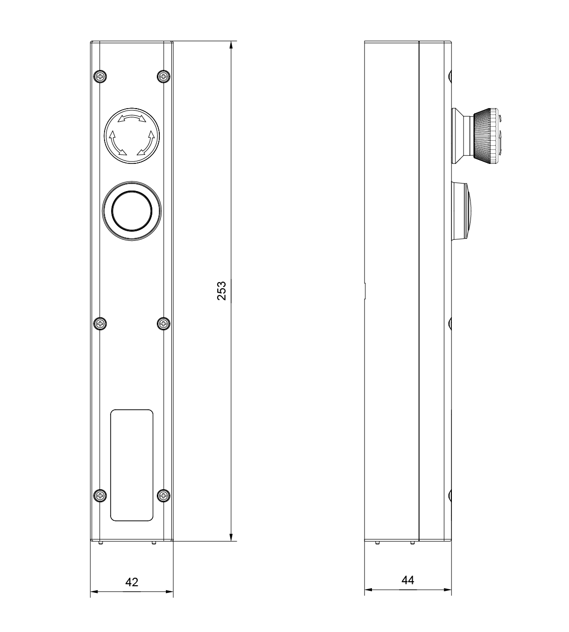
Dimensions
Height
44 mm
Length
253 mm
Width
42 mm
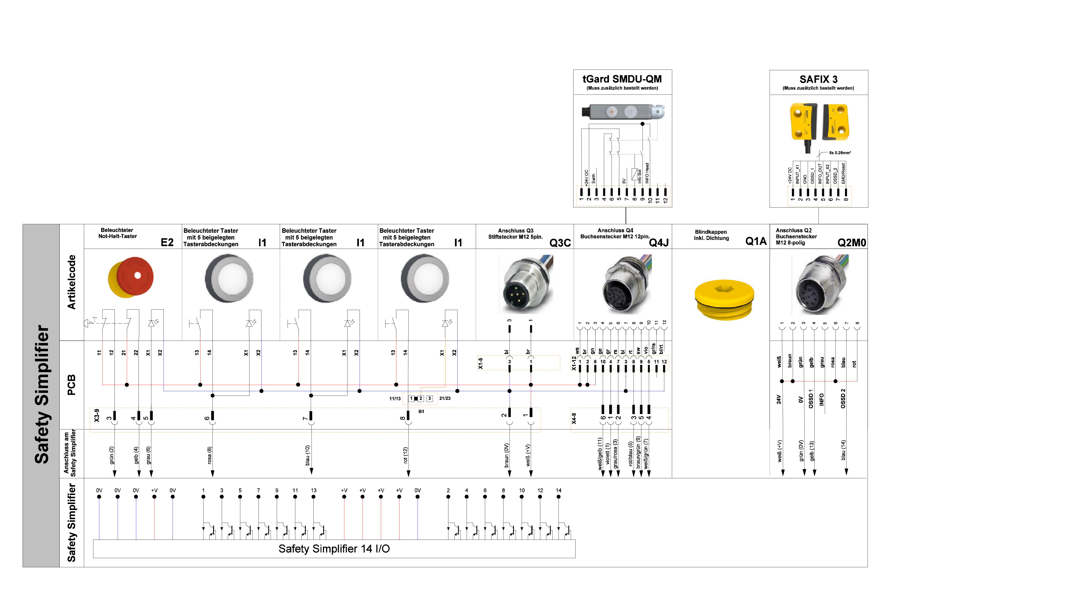
Electrical drawings
Connection example 1
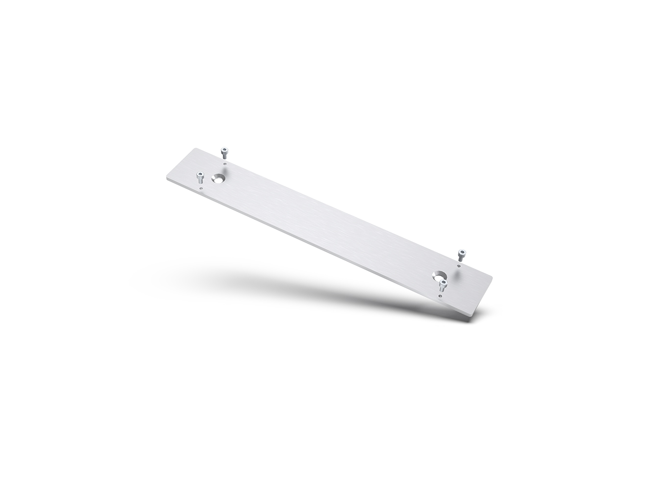
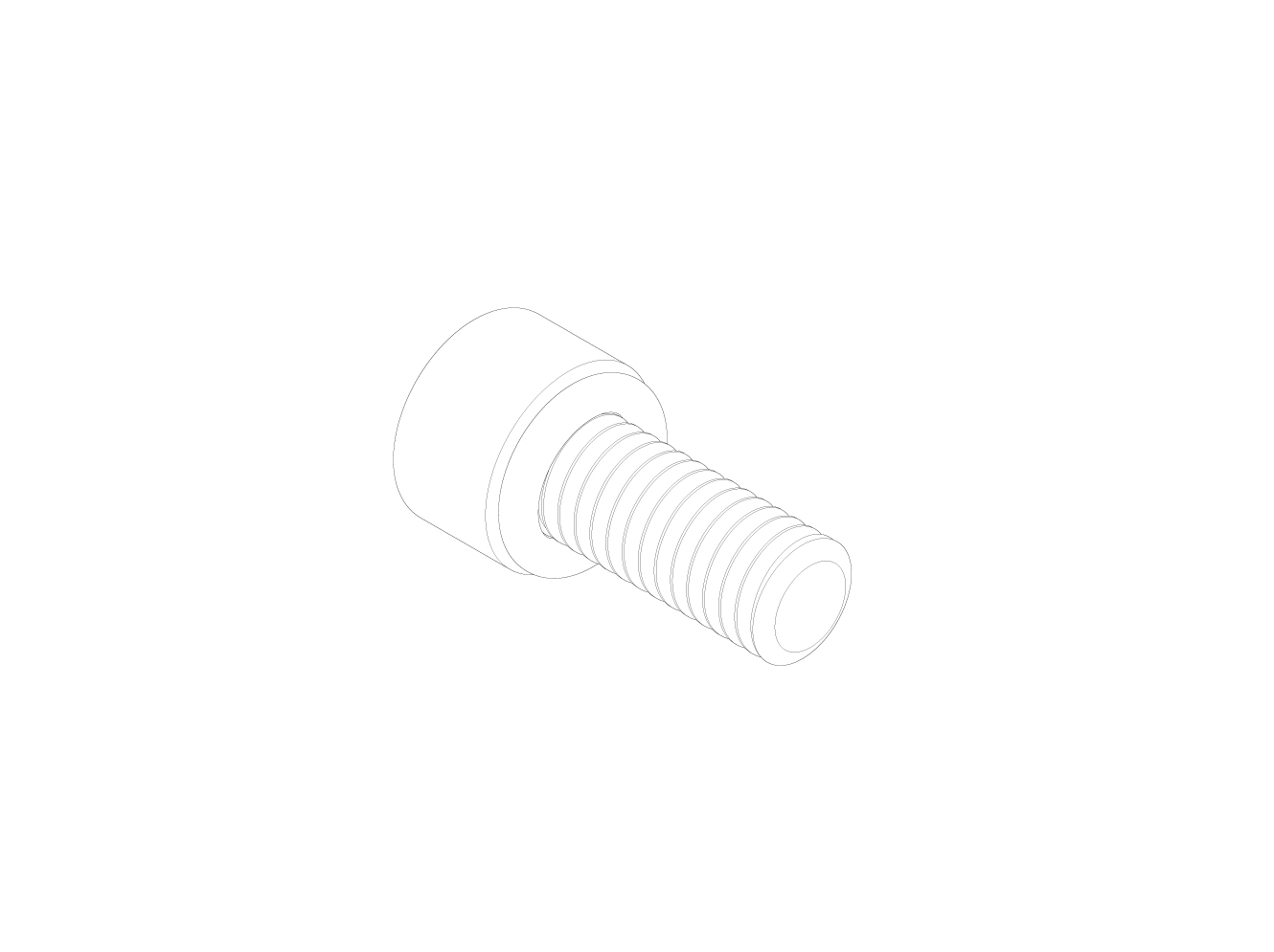
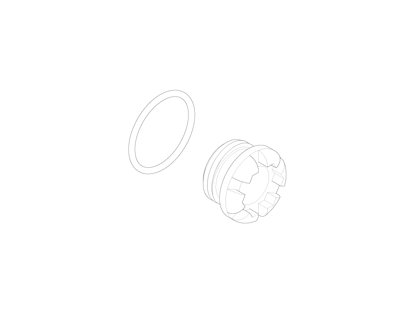
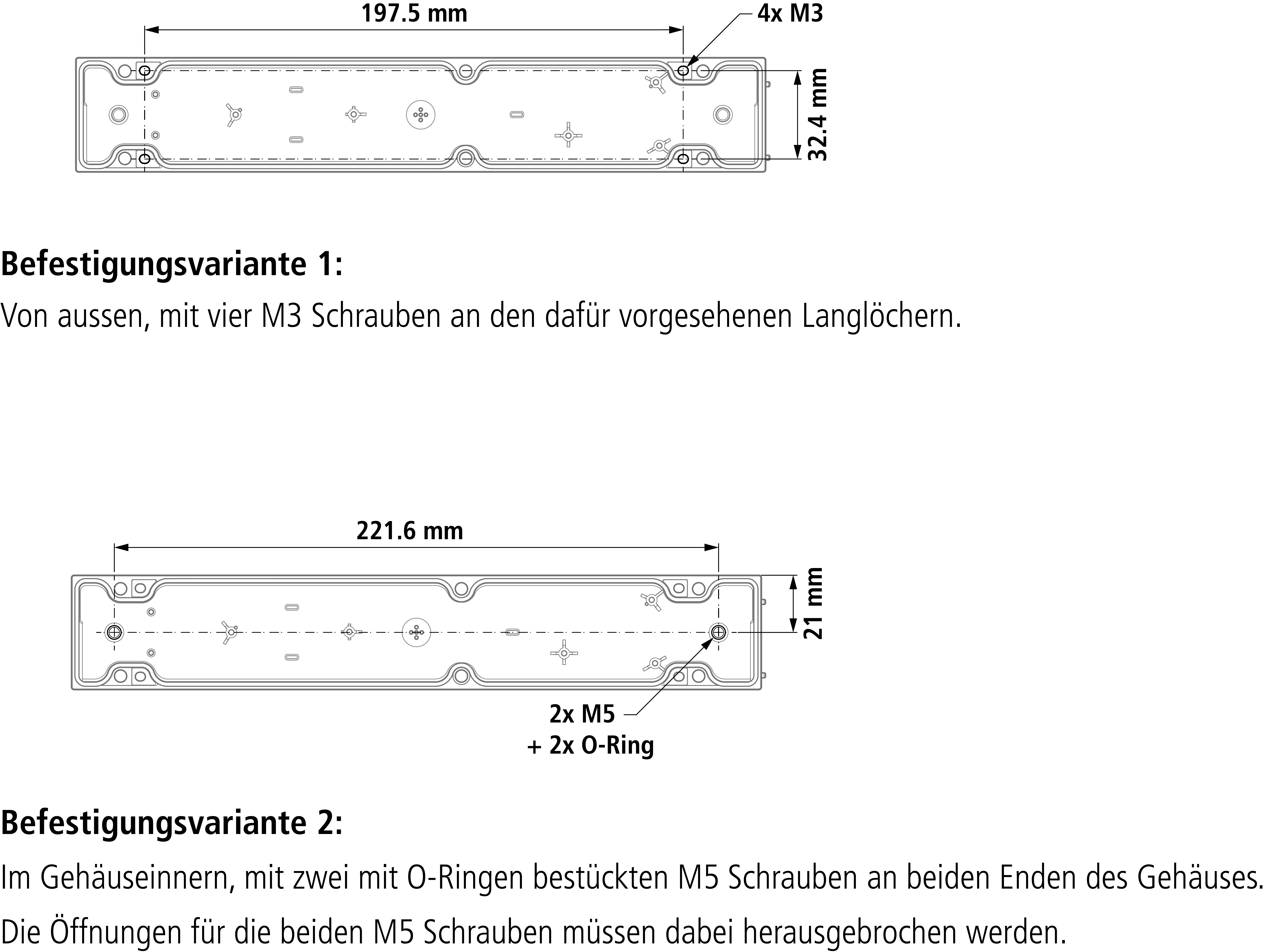
Drawings
Assembly 2
Dimensions